В одном из проектов использовал следующий механизм для управления бузером, включал его вручную, запускал таймер и выключал в прерывании, которое возникало при переполнении таймера. Со временем количество прерываний в проекте выросло и часто другие прерывания не давали сработать прерыванию, в котором выключался бузер. В результате чего, бузер всегда издавал разный по длительности звуковой сигнал. Для решения этой проблемы необходимо было отказаться от прерывания и аппаратно подавать импульс определенной длительности. Ниже приведен код который это делает.
Количество импульсов можно изменить, установив например 5.
I use an STM32F401C discovery board with STM32F401VCT6 microcontroller and want to set up a timer in one pulse mode, generating an interrupt after elapsed period. The interrupt handler is to toggle one of the outputs state.
I have generated the project, using STM32CubeMX, added the code starting timer and a callback to be invoked when an interrupt fires.
The line starting the timer operation in one pulse mode:
Unfortunately, the program does not work as desired — outputs’ state is not toggled.
The whole code of my main.c file is attached below. Clock configuration: APB1 Timer clocks: 25 MHz APB2 Timer clocks: 50 MHz
Could you please tell me, if I have missed something in my program?
main.c:
Edit: I attach the rest of the code, I find relevant.
stm32f4xx_hal_msp.c:
stm32f4xx_it.c:
2 Answers 2
I have finally figured out, what was missing in my code.
Apart from HAL_TIM_OnePulse_Start_IT() , also HAL_TIM_Base_Start() has to be called in order to set up the timer operation in one pulse mode.
Now my main function looks like below and the interrupt is fired when after the set time.

You haven’t shown us all the code. For example, where is the Timer and GPIO peripherals enabled? And where is the Timer interrupt enabled?
Typically with STM32Cube HAL applications, the functions like HAL_TIM_Base_Init() call another function like HAL_TIM_Base_MspInit() , which you may have to provide an implementation for. The xxx_MspInit() functions are typically implemented in a file called stm32xxxx_hal_msp.c. ST provides a template for this file with the HAL but I believe the expectation is that you will copy the template to your project file and customize it. (I’m not familiar with the STM32CubeMX tool, which might do some of this automatically.)
Typically within HAL_TIM_Base_MspInit() in stm32xxxx_hal_msp.c is where you will enable the timer and the timer interrupt. That code will look something like this:
Then you also need to provide an implementation for the timer interrupt handler. Typically this is done in a file called stm32xxxx_it.c. This is another file provided as a template with the HAL but you’re expected to customize it in your project directory. (And again, STM32CubeMX may do some of this automatically.)
It’s HAL_TIM_IRQHandler() which then calls your HAL_TIM_PeriodElapsedCallback() function.
So make sure you’ve enabled the timer and the timer interrupt in HAL_TIM_Base_MspInit() . Then make sure you’ve provided an implementation for TIM10_IRQHandler() which calls HAL_TIM_IRQHandler() . Then use the debugger to step through the code. Set breakpoints in HAL_TIM_Base_MspInit() and TIM10_IRQHandler() and HAL_TIM_PeriodElapsedCallback() to figure out what is working and what is not working.
Страницы
Ярлыки
воскресенье, 27 декабря 2015 г.
STM32 Timer One Pulse Mode


Timer one pulse mode
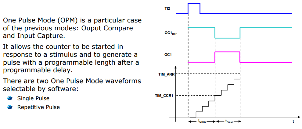
One pulse mode (OPM) is a particular case of the input capture mode and the output
compare mode. It allows the counter to be started in response to a stimulus and to generate
a pulse with a programmable length after a programmable delay.
To configure the timer this mode:
1. Configure the input pin and mode:
a) Select the TIxFPx trigger to be used by writing CCxS bits in CCMRx register.
b) Select the polarity of the input pin by writing CCxP and CCxNP bits in CCER
register.
c) Configure the TIxFPx trigger for the slave mode trigger by writing TS bits in SMCR
register.
d) Select the trigger mode for the slave mode by writing SMS = 110 in SMCR
register.
2. Configure the output pin and mode:
a) Select the output polarity by writing CCyP bit in CCER register.
b) Select the output compare mode by writing OCyM bits in CCMRy register (PWM1
or PWM2 mode).
c) Set the delay value by writing in CCRy register.
d) Set the auto reload value to have the desired pulse: pulse = TIMy_ARR —
TIMy_CCRy.
3. Select the one pulse mode by setting the OPM bit in CR1 register, if only one pulse is to
be generated. Otherwise this bit should be reset.
Delay = CCRy/(TIMx_CLK/(PSC + 1))
Pulse-Length = (ARR — CCRy)/(TIMx_CLK/(PSC + 1))
For more details on using the timer in this mode, refer to the examples provided in the
STM32xx standard peripheral libraries, in the /Project/STM32xx_StdPeriph_Examples/
TIM/OnePulse folder
void Init_TIM15(void)
<
RCC->APB2ENR |= RCC_APB2ENR_TIM15EN; // TIM15 clock enable (Master)
TIM15->PSC = PERIOD — 1;
TIM15->ARR = LCD_BUFFER_SIZE + PULSE — 1;
TIM15->CCR1 = PULSE; // Pulse_Output = ARR — CCR1
TIM15->CCMR1 |= (TIM_CCMR1_OC1M_0 | TIM_CCMR1_OC1M_1 | TIM_CCMR1_OC1M_2 | TIM_CCMR1_OC1FE); // PWM Mode2
TIM15->CR1 |= TIM_CR1_OPM; // Select One-pulse mode
TIM15->CR2 |= TIM_CR2_MMS_2; // MMS=100 Compare — OC1REF signal is used as trigger output (TRGO)
TIM15->EGR |= TIM_EGR_UG; // Update Generation
>
периодическая генерация
TIM1->CR1 = 0;
TIM1->CR2 = (4 TRGO
TIM1->PSC = 72 — 1;
TIM1->ARR = 500 — 1;
TIM1->EGR = (1
TIM1->CCMR1 = (OC_MODE_PWM2
TIM1->CCER = (1
TIM1->BDTR = (1
TIM1->CCR1 = 100;
TIM3->CR1 = 0;
TIM3->PSC = 72 — 1;
TIM3->ARR = 0xffff;
TIM3->EGR = (1
TIM3->CCMR1 = (OC_MODE_PWM1
TIM3->CCER = (1
TIM3->SMCR =
(0 ITR0 (TIM1)
| (4
TIM3->CCR1 = 40;
TIM3->CCR2 = 5;
TIM3->CR1 = (1
TIM1->CR1 = (1
однократная генерация
TIM1->CR1 = 0;
TIM1->CR2 = (4 TRGO
TIM1->PSC = 72 — 1;
TIM1->ARR = 500 — 1;
TIM1->EGR = (1
TIM1->CCMR1 = (OC_MODE_PWM2
TIM1->CCER = (1
TIM1->BDTR = (1
TIM1->CCR1 = 100 — 1; // на один такт меньше
TIM3->CR1 = 0;
TIM3->PSC = 72 — 1;
TIM3->ARR = 0xffff;
TIM3->EGR = (1
TIM3->CCMR1 = (OC_MODE_PWM1
TIM3->CCER = (1
TIM3->SMCR =
(0 ITR0 (TIM1)
| (5
TIM3->CCR1 = 40;
TIM3->CCR2 = 5;
TIM3->CR1 = (1
while(1)
<
if(pulse)
<
TIM3->CNT = 0xffff; // -1 для генерации события UR
TIM1->CR1 = (1
pulse = 0;
>
>
TIM15 to generate a delay, programmable width pulse, triggered by an external input. For the external input, I am using TIM3 routed to the appropriate pin (PA3) which is TIM15_CH2
static void TIM_Config(void)
<
TIM_TimeBaseInitTypeDef TIM_TimeBaseStructure;
TIM_ICInitTypeDef TIM_ICInitStructure;
TIM_OCInitTypeDef TIM_OCInitStructure;
GPIO_InitTypeDef GPIO_InitStructure;
/* TIM15 clock enable */
RCC_APB2PeriphClockCmd(RCC_APB2Periph_TIM15, ENABLE);
/* GPIOA clock enable */
RCC_AHBPeriphClockCmd(RCC_AHBPeriph_GPIOA, ENABLE);
/* TIM15_CH1 pin (PA.02) and TIM15_CH2 pin (PA.03) configuration */
GPIO_InitStructure.GPIO_Pin = GPIO_Pin_2 | GPIO_Pin_3;
GPIO_InitStructure.GPIO_Mode = GPIO_Mode_AF;
GPIO_InitStructure.GPIO_Speed = GPIO_Speed_50MHz;
GPIO_InitStructure.GPIO_OType = GPIO_OType_PP;
GPIO_InitStructure.GPIO_PuPd = GPIO_PuPd_NOPULL;
GPIO_Init(GPIOA, &GPIO_InitStructure);
/* Connect TIM pins to AF0 */
GPIO_PinAFConfig(GPIOA, GPIO_PinSource2, GPIO_AF_0);
GPIO_PinAFConfig(GPIOA, GPIO_PinSource3, GPIO_AF_0);
/* —————————————————————————
TIM15 configuration: One Pulse mode
The external signal is connected to TIM15_CH2 pin (PA03),
The Rising edge is used as active edge,
The One Pulse signal is output on TIM15_CH1 pin (PA02)
The TIM_Pulse defines the delay value
The (TIM_Period — TIM_Pulse) defines the One Pulse value.
————————————————————————— */
/* Compute the prescaler value */
PrescalerValue = (uint16_t) ((SystemCoreClock ) / 24000000) — 1;
/* Time base configuration */
TIM_TimeBaseStructure.TIM_Period = 65535;
TIM_TimeBaseStructure.TIM_Prescaler = PrescalerValue;
TIM_TimeBaseStructure.TIM_ClockDivision = 0;
TIM_TimeBaseStructure.TIM_CounterMode = TIM_CounterMode_Up;
TIM_TimeBaseInit(TIM15, &TIM_TimeBaseStructure);
/* TIM15 PWM2 Mode configuration: Channel1 */
TIM_OCInitStructure.TIM_OCMode = TIM_OCMode_PWM2;
TIM_OCInitStructure.TIM_OutputState = TIM_OutputState_Enable;
TIM_OCInitStructure.TIM_Pulse = 16383;
TIM_OCInitStructure.TIM_OCPolarity = TIM_OCPolarity_High;
TIM_OC1Init(TIM15, &TIM_OCInitStructure);
/* TIM configuration in Input Capture Mode */
TIM_ICStructInit(&TIM_ICInitStructure);
TIM_ICInitStructure.TIM_Channel = TIM_Channel_2;
TIM_ICInitStructure.TIM_ICPolarity = TIM_ICPolarity_Rising;
TIM_ICInitStructure.TIM_ICSelection = TIM_ICSelection_DirectTI;
TIM_ICInitStructure.TIM_ICPrescaler = TIM_ICPSC_DIV1;
TIM_ICInitStructure.TIM_ICFilter = 0;
TIM_ICInit(TIM15, &TIM_ICInitStructure);
/* One Pulse Mode selection */
TIM_SelectOnePulseMode(TIM15, TIM_OPMode_Single);
/* Input Trigger selection */
TIM_SelectInputTrigger(TIM15, TIM_TS_TI2FP2);
TIM15->BDTR |= TIM_BDTR_MOE; ///.
/* Slave Mode selection: Trigger Mode */
TIM_SelectSlaveMode(TIM15, TIM_SlaveMode_Trigger);
TIM_Cmd(TIM15, ENABLE);
>